
A Wheel-leg Biped (Two-legged) Robot
Main Prototype
A wheel-legged biped robot is a type of robot that combines both wheeled and legged locomotion. It has six servo motors, which are responsible for controlling the movements of its limbs and wheels. The robot's design includes knee joints, shoulder joints, and wheels, which allow it to move smoothly on different surfaces.
In addition to the servo motors, the robot also includes a battery pack to power its movements. The battery pack is an essential component of the robot, as it provides the energy required to power the servo motors and other electronic components. The battery pack should be selected based on the robot's weight and expected usage time.
The robot is also equipped with an IMU (Inertial Measurement Unit) sensor. The IMU sensor provides information about the robot's orientation and acceleration, allowing it to maintain balance while moving. This is especially important for a bipedal robot, which needs to balance its weight as it moves.
The knee joints are responsible for bending and extending the robot's legs, while the shoulder joints allow the robot's arms to move in a variety of directions. The wheels are attached to the robot's feet, allowing it to move quickly and smoothly on flat surfaces.
The robot's software is programmed to control the movements of the servo motors and interpret data from the IMU sensor. The software also includes algorithms for controlling the robot's balance and adjusting its movements based on changes in its environment.
Overall, the wheel-legged biped robot is a complex system that requires careful design and programming in Matlab simscape. By combining the benefits of wheeled and legged locomotion, this type of robot can move efficiently on a wide range of surfaces and navigate through challenging environments.
Simulating a wheel-legged robot design from SolidWorks in Matlab Simscape can be a powerful tool for evaluating the robot's performance and behaviour in a virtual environment. Here are some basic steps that can help ensure a good simulation at the end:
Create a 3D model of the robot in SolidWorks: The first step is to create a detailed and accurate 3D model of the robot in SolidWorks. This model should include all of the physical components, such as the servo motors, knee joints, shoulder joints, and wheels.
-
Import the SolidWorks model into Simulink: Once the 3D model is complete, it can be imported into Simulink using the “Simscape multibody Link” which plug-in. This allows the Solidworks model to be converted into a Simulink model that can be simulated in Simscape.
-
Define the robot's physical parameters: In Simscape, it is important to define the physical parameters of the robot, such as mass, dimensions, and material properties. This information can be used to accurately simulate the robot's movement and behaviour.
-
Create a simulation environment: In Simscape, a simulation environment can be created to test the robot's performance under various conditions. This environment should include the terrain or surface on which the robot will be operating, as well as any external forces or disturbances that may affect its movement.
-
Define the robot's control system: The robot's control system can be defined using Simulink blocks and models. This includes the algorithms and equations that govern the robot's movement and behaviour, as well as any sensors or feedback loops that are used to control its actions.
-
Run the simulation: Once the simulation is set up, it can be run to evaluate the robot's performance. This can include testing its ability to move over different terrain types, its speed and agility, and its ability to maintain balance and stability.
By following these steps, it is possible to create a detailed and accurate simulation of a wheel-legged robot design from SolidWorks in Matlab Simscape. This simulation can be a powerful tool for evaluating the robot's performance and behaviour in a virtual environment, allowing for iterative design improvements and optimization.


The overall idea of the robot is explained clearly in the above picture. The decision to use 3 motors per side in the wheel-legged robot design is based on a trade-off between mechanical complexity and energy efficiency. While it may be more difficult to manage and control, using 3 motors per side can offer several benefits over a design with only 2 motors per side. With 3 motors per side, the robot can achieve greater control and precision in its movements. Each motor can be independently controlled, allowing for finer adjustments in the robot's balance and movement. This is particularly important for a bipedal robot, which requires careful balance and coordination to walk effectively. In addition, having 3 motors per side allows the robot to distribute its weight more evenly, which can help improve stability and reduce the risk of falls or tipping. This can be especially important when navigating uneven terrain or obstacles. While using 2 motors per side may require less energy overall, it can also be more mechanically complex to ensure that the bottom part of the leg is lifted up in the correct way when crossing an obstacle. This could require additional mechanisms or sensors to ensure that the robot can navigate terrain effectively. Given the circumstances and timeline, opting for the design with 3 motors per side may be the more practical and feasible option. While it may require more effort and skill to manage and control, it can offer greater precision and stability in the robot's movements, making it more effective for navigating different environments and completing tasks.
The Solidwork model and the view is given below in the figures.

Figure 31: Isometric view of the wheel legged biped robot in Solidwork. (Normal mode)

Figure 32: Front view of the wheel legged biped robot in Solidwork. (Normal mode)

Figure 33: Isometric view of the wheel legged biped robot in Solidwork (Retracted mode)
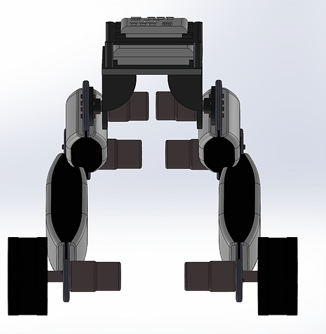
Figure 33: Front view of the wheel legged biped robot in Solidwork. (Retracted mode)

Figure 34: Front view of the wheel legged biped robot in Solidwork. (Retracted mode)

Figure 35: Front view of the wheel legged biped robot in Solidwork. (Retracted mode)

Figure 36: IMU sensor and the Battery of wheel legged biped robot in Solidwork.

Figure 37: Motor mount connect to the legs in wheel legged biped robot in Solidwork.

Figure 38: Wheel connected to the motor and the legs of robot in Solidwork.

Figure 39: Shoulder joint of the wheel legged biped robot in Solidwork.
The designed two-wheeled robot using Solidworks, and also have provided figures that show all the components and the overall body of the robot. The figures depict a realistic representation of the robot, taking into consideration the dynamics of the design.
The design of the robot likely includes various components such as the two wheels, motor controllers, batteries, sensors, and other electronic components. The body of the robot is likely designed to be sturdy and lightweight, using materials such as aluminium or carbon fibre.
The figures that you have provided likely show the robot in different views and angles, highlighting the various components and their placement within the overall design. The figures may also include annotations or labels to help identify specific parts or components. The design of the two-wheeled robot using SolidWorks and the accompanying figures demonstrate a comprehensive understanding of the dynamics and functionality required for a successful robot design.