

Modelling Contact force between two solids

The “Spatial Contact Force” which was introduced in recently by Matlab. The contact between the geometries connected to a set of solids is modelled by the Spatial Contact Force block. To model a contact, you can either create your own normal and friction force laws or use the built-in penalty technique. The link is given below to study further more about new contact force.
The illustration demonstrates how a spatial contact issue is modelled by the Spatial Contact Force block. A blue base geometry and a red follower geometry are in touch in this instance.

Figure 15: Spatial contact force
Each geometry has a contact frame during the interaction. Always coincident and situated at the contact point are the two contact frames. The contact frames' z-direction is an inward normal vector for the follower geometry, but an outward normal vector for the base geometry. As the contact point changes during continuous contact, the contact frames move around the geometry.
According to Newton's Third Law, the block exerts contact forces on the shapes at the contact frames' origin:
To comprehend the new contact force notion, created a straightforward mechanism in Matlab Simulink utilising the Simscape Multibody environment. The goal of the mechanism, which consisted of a wheel and a solid rod, was to create a rolling wheel after touching it at an angle of 5 degrees with the solid plane. The primary code, which contained the necessary physical parameters and simulation's starting points is given below in figure 16.

The contact force is connected with the cylindrical wheel and the inclined plane as those are the main two components. The cylindrical wheel is connected with the free wheel joint as it rolling on the incline plane. The 6-DOF joint (Free wheel joint) will be further explain in the main robot.
Figure 16: Main spatial contact force example

The simulation block includes the representation of normal force and frictional force between the wheel and the solid rod. The normal force helps to prevent penetration by pushing the geometries apart, while the frictional force opposes the tangential velocities between the shapes. This simulation block helps to better understand the contact force and how it can be applied in designing rolling wheels for a two-wheel biped robot.
Figure 17: Spatial contact force block
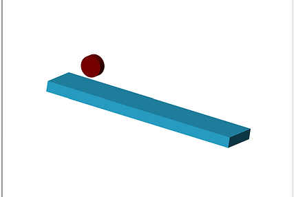
Figure 18: Example for spatial contact force
The tutorial has resulted in a successful outcome as the steps were followed correctly and the expected result was achieved.